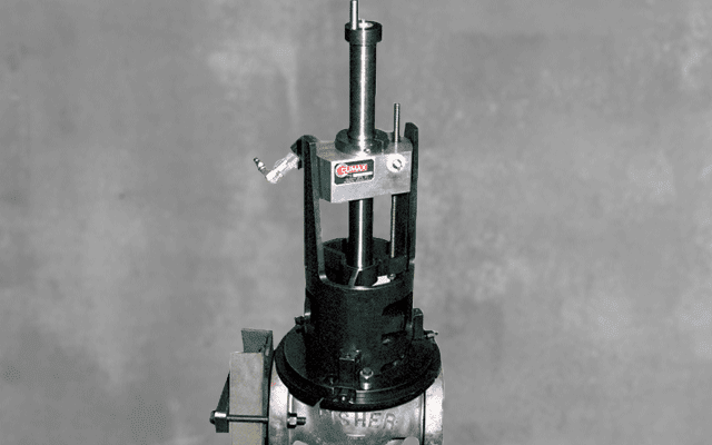
VM8000 GLOBE AND CONTROL VALVE REPAIR
Designed to bore, face and thread Fisher and Dresser Masoneilan control valves or comparable configurations from 3 to 10 inches (76.2 to 254 mm) in diameter.Specification:
Valve Seat Diameter: 2.5 – 10 in. (6.35 – 254.0 mm)Valve Throat Diameter: 3 – 10 in. (76.2 – 254 mm)
Power Option: Pneumatic or Hydraulic
Product Advantages
CAPABILITIES
The VM8000 is designed for on-site machining of seats and seal areas of Fisher and Dresser Masoneilan (or any other, similar type) control valves. The machine mounts directly on the valve and bores throat areas from 2.5 – 10 inches (63.5 – 254 mm) in diameter.
It refaces seats up to .75 inches (19.05mm) wide without tool bit adjustment. The machine can reach 16 inches (406.4mm) from the top to the valve body and has a boring stroke of 10 inches (254mm). The machine cuts nearly any kind of finish from fine to 40-pitch scroll for gasket seals.
With the Model VM8000 Valve Repair Machine, the repair operation consists of removing the valve bonnet and stem assembly, applying a stainless weld buildup in the valve seat and seal areas and machining to the manufacturer’s original specifications. The original in-line welds are not disturbed and need no recertification.
FEATURES
Components of the VM8000 include the main body, rotational drive unit, turning bar, mounting fixtures and tool holder set. Machining torque is delivered through the rotational drive unit, which may be either hydraulically or pneumatically driven.
The axial feed system is manually controlled. Calibrated in .001 inches (.0254mm) increments, the feed dial can be zeroed to cut precise depths specified by the manufacturer.
The boring diameter is set with the manual hand wheel on top of the bar. Make multiple boring passes without removing the machine for tool adjustments.
Pin locators in the mounting plates allow accurate repositioning of the machine’s main body during multiple setups.
Because the turning bar rotates in close tolerance needle bearings, the machine is capable of high precision machining.
During boring operations, the total indicated runout (TIR) will not exceed .002 inches (.0508mm) over the entire stroke.
With the long turning bar, deep valve machining is possible. The rack-actuated tool head radial feed is automatic at .003 inches (.076mm) per revolution, or manual at .025 inches (.635mm) per revolution.
Precision machining is achieved with the calibrated radial feed dial located on top of the turning bar.
SETUP AND OPERATION
Remove the valve’s the bonnet and stem and mount the Model VM8000 base plate. Attach, center and level the intermediate plate and main body assembly. Cut the necessary weld preps, making sure old weldments and all corrosion is removed. Remove the VM8000 and apply weld buildup as needed. Using the pin locator system, the machine is reattached to the intermediate plate in perfect alignment for finish machining all seat and seal areas. The tool bit remains visible during machining operations so the operator has excellent control of all precision boring and facing operations.
Downloads

